In modern bulk material handling, the pneumatic conveying roots blower has become the workhorse for moving chemically unstable powders, flakes, and granules through enclosed pipelines. When the process demands oxygen isolation, explosion protection, or moisture control, the optimal solution is a closed-loop dilute-phase conveying system powered by a roots rotary lobe blower operating at 29.4–196 kPa. This article explains why a positive displacement blower is uniquely suited for this duty, how the closed-loop concept works, and what engineering considerations ensure long-term reliability.
Why a Roots Blower Is the Ideal Air Mover for Pneumatic Conveying
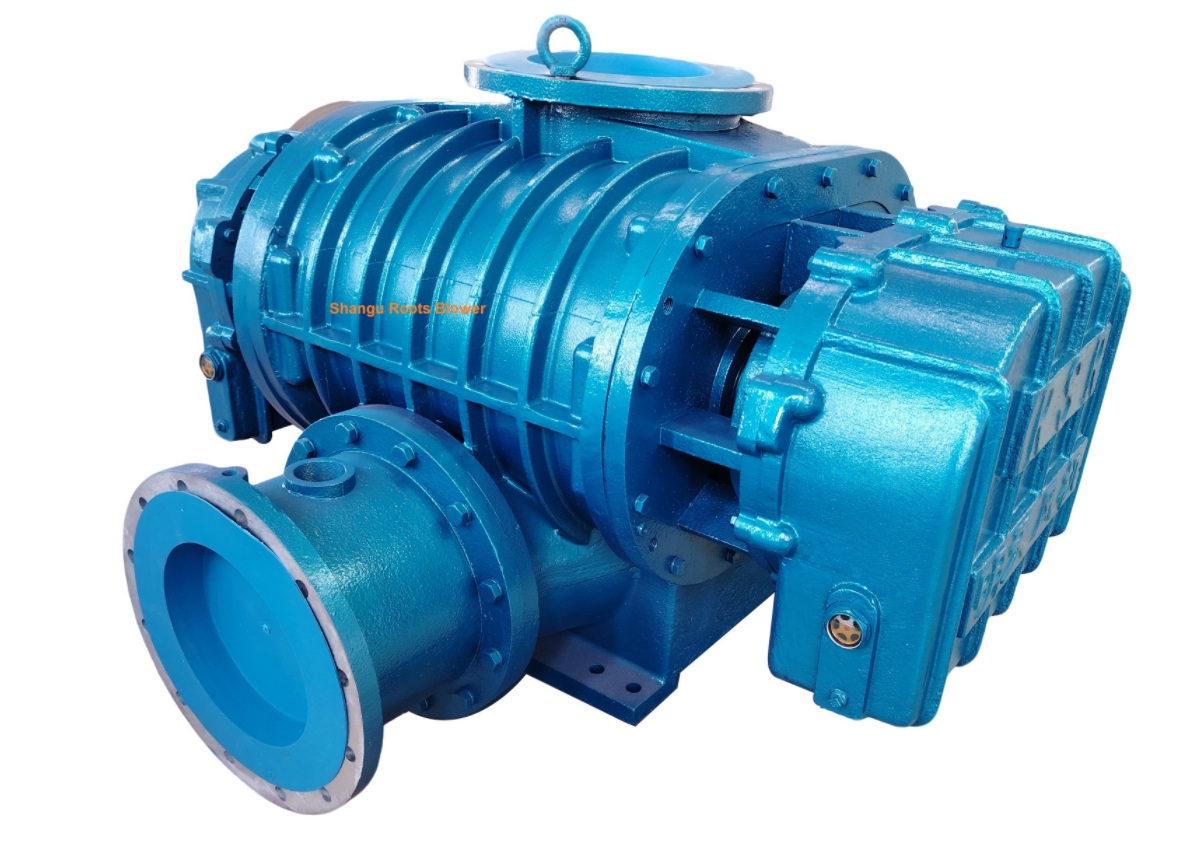
A roots blower is a type of pneumatic conveying roots blower that traps a fixed volume of gas per revolution and transfers it from the inlet to the outlet. Two synchronized, non-contact rotors (commonly three-lobe in modern designs) create sealed pockets that move the gas against system backpressure. Because the delivered flow remains nearly constant regardless of downstream resistance, a roots rotary lobe blower maintains the stable air velocity required to keep materials suspended in dilute-phase conveying — something centrifugal blower cannot guarantee.
Key advantages in pneumatic conveying duty:
Constant volumetric flow despite fluctuating material loading
Oil-free delivery — the compression chamber is non-contacting, so no lubricant contaminates the gas stream
Pressure range 29.4–196 kPa (0.3–2.0 bar g) perfectly matches dilute-phase requirements
Dual-function capability — one machine acts as both a pressure blower (on the feed side) and a vacuum pump (suction side) in a closed loop
Simple, rugged construction tolerant of the vibration and thermal cycling inherent in 24/7 conveying service
💡 In a closed-loop system, the Pneumatic Conveying Roots Blower‘s ability to handle both pressure and vacuum without modification is what makes the recirculation concept physically possible.
The Closed-Loop Inert Gas Conveying Concept
Conventional pneumatic conveying systems are open — the carrier gas (usually air) is released to atmosphere after material separation. However, when the process demands nitrogen (N₂), carbon dioxide (CO₂), or argon as the conveying medium, releasing the gas after every cycle becomes economically unsustainable. This is where closed-loop pneumatic conveying proves its value.
System workflow:
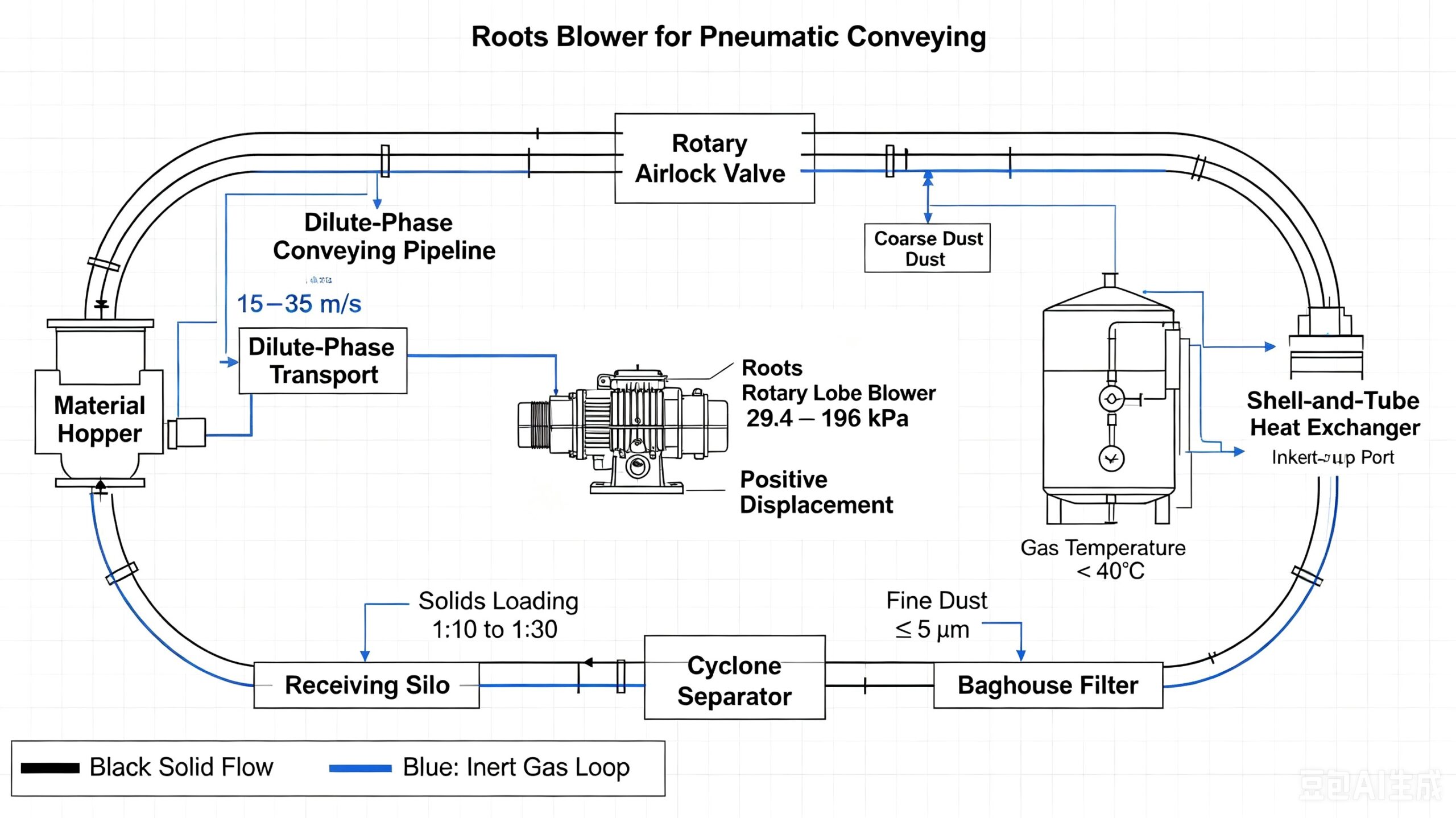
Metering Feed: Material drops from the feed hopper into a rotary valve (rotary airlock). The valve’s chambers fill by gravity and discharge a measured volume into the conveying line while maintaining gas-tight isolation.
Pressure Boost: The pneumatic conveying roots blower compresses the recirculated inert gas to 29.4–196 kPa and pushes it into the feed point.
Dilute-Phase Transport: The gas stream, at 15–35 m/s, suspends the material and carries it through the pipeline to the destination silo. Solids loading ratio typically ranges 1:10 to 1:30 (dilute phase).
Gas-Solid Separation: At the receiving silo, a cyclone removes coarse particles, followed by a baghouse filter (≤ 5 µm filtration) for fine dust.
Gas Recirculation: The cleaned inert gas returns to the roots blower inlet, completing the loop. Make-up gas compensates only for trace leakage (< 5%/day).
This architecture allows the same positive displacement blower to act simultaneously as a booster on the pressure side and an extractor on the suction side — the defining feature of closed-loop design.
Why Chemically Unstable Materials Demand This Configuration
Many industrial materials degrade, react, or become hazardous when exposed to ambient air:
| Material Category | Risk in Open Air | Closed-Loop Benefit |
|---|---|---|
| Reactive metal powders (Mg, Al, Ti) | Oxidation, pyrophoric ignition | O₂ < 1% via N₂ blanket |
| Pharmaceutical intermediates | Moisture absorption, decomposition | Controlled dew point |
| Food-grade powders (vitamin C, enzymes) | Oxidative spoilage | Extended shelf life |
| Flammable dusts (sulfur, coal, organic peroxides) | Explosion risk | Inert atmosphere eliminates ignition triangle |
| Electronic materials (LiFePO₄ cathode) | Fe²⁺ oxidation | Preserves stoichiometry |
| Flakes & brittle granules | Attrition in high-velocity dense phase | Low-velocity dilute phase minimizes breakage |
The 29.4–196 kPa pressure window is deliberately chosen: high enough to overcome pipeline resistance and elevation, yet low enough to keep gas velocity in the dilute-phase regime — protecting fragile flake and granule geometries from excessive attrition.
Critical Engineering Considerations for pneumatic conveying roots blower
While the concept is elegant, recirculating gas introduces challenges that must be addressed during design:
1. Gas Temperature Management
Each compression pass raises gas temperature by 10–15°C. In a closed loop, this heat accumulates. Without intervention, steady-state inlet temperatures can reach 60–80°C, causing rotor thermal expansion, material degradation, and pressure drift.
Solution: Install a shell-and-tube heat exchanger (typically water-cooled) in the loop to maintain gas temperature below 40°C. Position the cooler either upstream or downstream of the roots rotary lobe blower.
2. Fine Dust Carry-Over Protection
Micro-fines that escape the baghouse can re-enter the positive displacement blower, accelerating rotor and timing gear wear.
Solution: Specify a high-efficiency final filter (HEPA or equivalent) on the blower suction. Consider hard-chrome or tungsten-carbide rotor coatings for abrasive duties — extending service life from 12–18 months to 36+ months.
3. Seal Integrity at the Rotary Valve
The rotary airlock operates at the interface between atmospheric pressure (hopper) and pressurized loop. Conventional labyrinth seals allow inert gas leakage.
Solution: Implement packing gland seals with nitrogen purge, or upgrade to mechanical seal construction for zero-leakage service.
4. Loop Pressure Balance & Safety
Dynamic pressure distribution (slightly positive at feed, slightly negative at silo, highest in mid-line) demands active management.
Solution: Fit pressure transmitters with PLC interlocks, relief valves, and a make-up gas inlet at atmospheric reference point to compensate for leakage and prevent vacuum formation at the blower suction.
5. Initial Inerting & Purge Sequence
At start-up, the pipeline contains air. Oxygen must be displaced before material introduction.
Solution: Program an automatic N₂ purge cycle (target O₂ < 3%) prior to rotary valve activation. On shutdown, execute a reverse sequence — stop feed, continue gas flow to clear the line, then secure the blower.
Selecting the Right Roots Blower for Your Conveying System
Proper sizing of a pneumatic conveying roots blower requires:
- Material properties: bulk density, particle size distribution, flowability, abrasiveness
- Throughput target (tons/hour)
- Pipeline geometry: horizontal length, vertical lift, number of bends
- Required conveying velocity (typically 1.5–2× saltation velocity)
- Gas type and initial oxygen specification
- Ambient conditions and altitude
As a rule of thumb for the 29.4–196 kPa range:
- 29.4–98 kPa: Single-stage tri-lobe roots blower
- 98–196 kPa: Two-stage series configuration or heavy-duty high-pressure rotary lobe blower
Modern roots rotary lobe blower packages achieve volumetric efficiency up to 92%, with noise levels reduced by 20 dB(A) compared to legacy two-lobe designs. Adding a VFD (variable frequency drive) can yield 25% energy savings by matching blower speed to real-time demand.
Applications Across Industries
The closed-loop Pneumatic Conveying Roots Blower powered conveying system serves diverse sectors:
- Chemical & Pharmaceutical: Active pharmaceutical ingredients, catalysts, pigments
- Battery Materials: Lithium iron phosphate, graphite, silicon anode powders
- Metallurgical Powders: Aluminum, magnesium, titanium, zirconium powders
- Food & Nutraceutical: Antioxidant-sensitive powders, enzyme preparations
- Agrochemicals: Sulfur, pyrophyllite, organophosphate granules
- Recycled Materials: Fine plastic flakes, rubber powder
Frequently Asked Questions
Q: Can a roots blower handle both pressure and vacuum in the same closed loop?
A: Yes. A positive displacement blower naturally generates overpressure at the discharge and suction at the inlet. In a closed-loop configuration, the same machine pressurizes gas entering the conveying line while simultaneously drawing gas back from the receiving silo — eliminating the need for separate blower and vacuum pump units.
Q: What pressure range is typical for dilute-phase closed-loop conveying?
A: The 29.4–196 kPa (0.3–2.0 bar g) range covers the vast majority of dilute-phase inert gas applications. Below 29.4 kPa, material suspension becomes difficult; above 196 kPa, the economics shift toward dense-phase systems using screw compressors.
Q: How much inert gas is consumed in a closed-loop system?
A: Only leakage losses, typically < 5% of loop volume per day. A make-up gas inlet controlled by a pressure regulator replenishes the loop automatically.
Q: What rotor coating is recommended for abrasive materials?
A: Hard chrome plating (0.05–0.10 mm) extends rotor life to 36+ months. For extreme abrasion (cement, fly ash, silica), specify tungsten carbide coating.
Q: Is a heat exchanger mandatory in closed-loop systems?
A: Strongly recommended. Compression heating in a recirculating loop will raise gas temperature to unacceptable levels without active cooling. A shell-and-tube exchanger maintaining < 40°C inlet temperature is standard practice.
Ready to Specify Your Roots Blower?
Tell us what you convey and we’ll tell you how. Share your material, capacity, and pipeline layout — get a matched pneumatic conveying roots blower recommendation with performance curve and quote in 48 hours.
Contact our product manager Mr.Vincent Huang for a satisfied proposal | Email:vincent@cnrootsblower.com