Ash Silo Gasification Roots Blower: The Key to Clog-Free Fly Ash Discharge
Coal-fired power plants generate massive amounts of fly ash every day. The typical chain—electrostatic precipitator hopper → roots blower→ pneumatic conveying → ash silo storage → bulk truck loading—usually breaks down not at the conveying stage, but at the very last moment of silo discharge. Under long-term gravitational compaction, fly ash hardens, “bridges,” and arches. The discharge valve keeps spinning, but no ash comes out.
In our previous discussion on ash silo / hopper gasification (fluidization), we covered the basic principle: push heated, dried compressed air into the fluidization trough so the ash layer above the porous plate becomes fluidized and slides toward the outlet. Within this chain, the equipment that “pushes the air in” is almost universally specified as a roots blower.
This article explains the principle end-to-end, clarifies the role of the ash silo gasification roots blower, provides a process flow diagram with the blower included, and offers practical selection and service roots blower guidance for plant operators and procurement teams.
Quick Recap: What the Ash Silo Gasification System Does
At the bottom cone of the ash silo (or ESP hopper), fluidization troughs are arranged radially. The trough surface is a fluidization plate (typically silicon-carbide sintered porous plate). During operation:
- A roots blower pressurizes ambient air and delivers it downstream
- An electric heater raises and dries the air (typically 80–150°C / 176–302°F)
- Hot air seeps uniformly through the micropores of the fluidization plate, forming an air film between ash particles
- The fly ash shifts from static pile to liquid-like fluidized state; the angle of repose drops sharply, and ash slides along the 6°–15° trough slope toward the discharge outlet
In flat-bottom silos, fluidization troughs are usually arranged radially, covering ≥15% of the silo base area, with a specific air consumption of about 0.62 Nm³/(m²·min).
Within this system, the blower is not the “star”—but if the blower is wrong selected, heating and fluidization both fail.
Why a PD Blower (Roots Blower) Is the Industry Standard
In ash silo gasification, the pd blower (positive displacement blower) is specified almost by default. Comparing a roots unit with a centrifugal fan makes the reason obvious:
| Comparison | Roots Blower | Centrifugal Fan |
|---|---|---|
| Flow characteristic | Constant flow, minimally affected by back-pressure fluctuation | Surge-prone near peak of curve |
| Pressure range | Single-stage 9.8–98 kPa, covers 8–15 kPa gasification need | Low-pressure type usually <10 kPa; inefficient if deeper |
| Dust tolerance | Tolerates slight ash backflow, rugged | Impeller wear-sensitive |
| Maintenance | Simple structure, few wear parts, in-house serviceable | Strict dynamic balance required |
| Noise | 3-lobe design + silencer acceptable | Quieter but higher cost tier |
The back-pressure of a gasification system = fluidization plate resistance + ash bed resistance + pipeline loss, totaling only 3–8 kPa, but requiring stable flow, no surging, and 24/7 continuous operation—exactly where the “tough character” of a roots blower fits.
Three Specific Roles of the Roots Blower in the System
① Stable air supply to support the fluidization film
The fluidization plate micropores are only tens of microns wide. They rely on the low-pressure, high-volume air from the roots blower compressor to “bubble” evenly. Insufficient flow → film fails → dead ash zones; excess flow → dust entrainment → overloads the baghouse above. The constant-flow nature of the roots machine shines here.
(Note: A roots blower is technically a positive displacement compressor operating in the low-pressure range. In industry it is called both a “roots blower” and a “roots blower compressor.”)
② Works with the heater to deliver dry hot air to the cone
The air from the roots outlet is essentially at ambient temperature, then enters the electric heater to reach 80–150°C before entering the silo. Key point: the air delivered by the roots blower is inherently dry (no cooling/dehumidification stage beforehand); the heater only raises temperature, not re-dehumidifies—don’t confuse this with a “cool-then-reheat” setup.
③ One-duty-one-standby / three-running-one-standby for continuity
A typical configuration for 3 ash silos (2 coarse + 1 fine) uses 4 roots blowers + 4 heaters, three running and one standby. If any unit fails, the standby takes over. Advanced setups parallel plant instrument air + receiver tank at the roots outlet as emergency backup—when roots pressure drops below threshold, the system auto-switches to backup air so fluidization never stops.
Process Flow Diagram with Ash Silo Gasification Roots Blower (Standard)
This is the most common configuration for 300 MW / 600 MW units in China; it can be used directly for P&ID drawing:
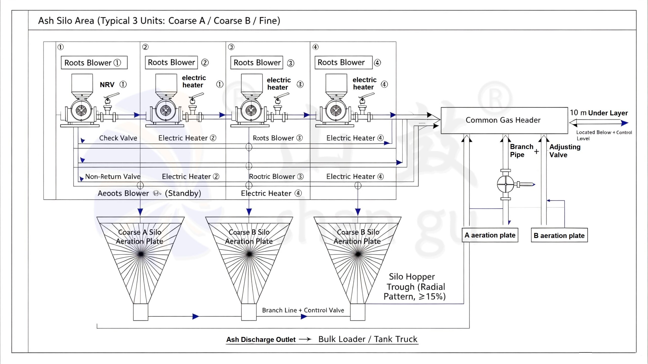
Node explanation:
Roots blower: flow per silo sized individually; small/medium silo 5–15 m³/min, large silo >1000 m³ uses 15–30 m³/min, pressure 8–15 kPa with 10%–15% margin
Check valve: prevents high-temp air from heater flowing back and burning the blower
Electric heater: placed close to the silo; heats to 80–150°C; heater should be near the silo layout
Header: below the 10 m level, one main pipe splits to three silos, each branch with adjustable valve
Fluidization plate: silicon carbide sintered, mounted on trough, trough bottom slopes 6°–15° toward discharge
Common pitfall: placing the heater too far from the silo → pipeline heat loss → insufficient temperature at the plate → ash still damp. Standards state “heater shall be close to silo/hopper,” not randomly at the 6 m level.
Selection & Service Roots Blower: Practical Points
Lock in these three selection parameters first:
1.Flow → fluidization trough total area × 0.62 Nm³/(m²·min), then × 1.1–1.15 margin
2.Pressure → system resistance 3–8 kPa + margin, set 8–15 kPa class (taller silo / thicker ash bed takes upper limit)
3.Quantity → three silos four blowers (three running one standby) is industry norm; single silo can use one duty one standby
Two most-overlooked maintenance items:
The roots blower inlet must have an air filter; otherwise ash backflow into the rotor widens clearance and drops flow
Heater and roots interlock: blower not started → heater forbidden; blower trip → heater interlocked off, or it dry-burns
Quick fault diagnosis:
| Symptom | Likely cause |
|---|---|
| Plate partially not bubbling | A roots unit tripped / branch valve closed / plate micropore clogged |
| Silo still arching | Heating temp insufficient (below dew point) / trough area <15% |
| Roots Blower high current | Filter clogged / abnormal heater-side backpressure / tight rotor clearance (oil lack) |
FAQ
Q: What is an ash silo gasification roots blower used for?
A: It supplies low-pressure, constant-flow compressed air to the fluidization troughs at the bottom of coal-plant ash silos, keeping fly ash fluidized so it discharges without bridging or hardening.
Q: Why use a roots blower instead of a centrifugal fan for ash silo gasification?
A: A roots (PD) blower delivers constant flow under fluctuating back-pressure, tolerates minor ash backflow, and runs 24/7 with simple maintenance—ideal for the 3–8 kPa stable-demand gasification duty.
Q: What pressure and flow does a roots blower compressor need for ash silo fluidization?
A: Typically 8–15 kPa pressure with 10%–15% margin, and flow based on trough area × 0.62 Nm³/(m²·min) × 1.1–1.15. Large silos often need 15–30 m³/min per roots blower.
Get a Custom Roots Blower Quote for Your Ash Silo
The ash silo gasification system is simple in principle but difficult in running trouble-free for years. The roots blower dominates this niche not by flashy specs, but by three traits that hit maintenance pain points: constant flow + ruggedness + easy service.
For new desulfurization/ash-handling projects or old-silo retrofits needing a replacement ash silo gasification roots blower, lock in these three rules first: calculate flow by trough area, leave enough pressure margin, and use three-duty-one-standby. Then the heater and plates can perform.
Not sure about flow or pressure? Send us your silo volume, coarse/fine ash ratio, and discharge cycle—we’ll reverse-calculate using 0.62 Nm³/(m²·min) and provide a service roots blower proposal with spare-part plan.
👉 Contact our engineering team for PD blower selection, OEM replacement, and worldwide service roots blower support.